A1X
PAGE
Last updated: 06
MAR 2006
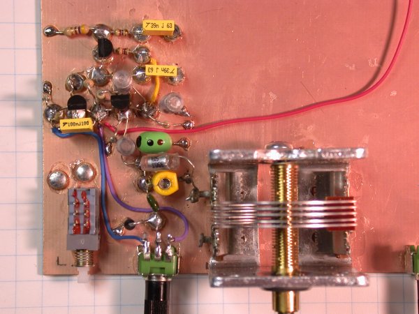
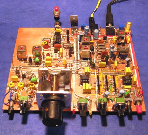
A 40M QRP rig being
built Manhattan style and ugly by a few for a future article in the ARCI
"QRP Quarterly."
http://www.qrparci.org
|
File
or Document
|
Type
|
Last
Update
|
Status/Comments
|
| A1X Schematic |
.pdf |
12FEB2006
|
Updated for Update #1 and new VFO values |
| A1X Update #1 |
.pdf |
26JAN2006
|
The NA5N Manhattan layout scheme |
| A1X B.O.M. |
-- |
--
|
Coming soon, probably in both .pdf and Excel formats |
| A1X
OSC |
.pdf |
16FEB2006
|
Spectrum Analyzer displays of the VFO, BFO and TXO |
|
|
|
|
Other possible nifty stuff
#XTAL TEST SET
The crystal test set built for evaluating the A1X 5MHz crystals.
Links
Bill Kelsey N8ET
Tony Fishpool G4WIF
Graham Firth G3MFJ
Craig Johnson AAØXX
The
Latest Images 4 Mar 2006
 <
>
<
>
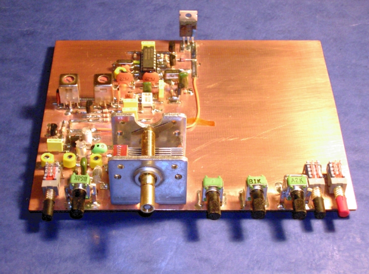
Added 2nd IF can for tuned input/tuned output RF amplifier. The receiver
is virtually complete. Awaiting the standard HC-49U
5MHz crystals (backordered another week from Mouser) to determine final
values on IF amplifier and crystal filters. Will take
a better shot later. (Didn't have my good camera or tripod with me
for a good exposure).
The
NA5N Build steps and progress
 <
>
<
>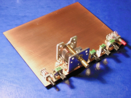
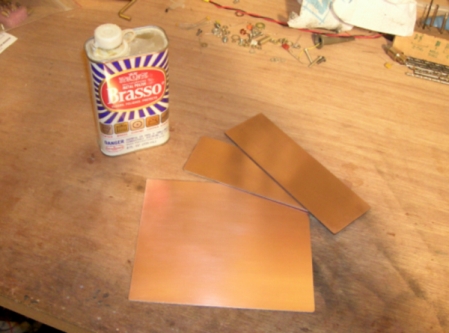
(2-06-2006) Pieces cut for the main board and front and rear panels.
(2-06-2006) Front panel controls mounted.
Material is .062" double sided copper clad.
(2-06-2006) The VFO, BFO, TXO, TX Mixer (ADE-1), TX filter (IF cans),
T/R switching and +8v regulator built.
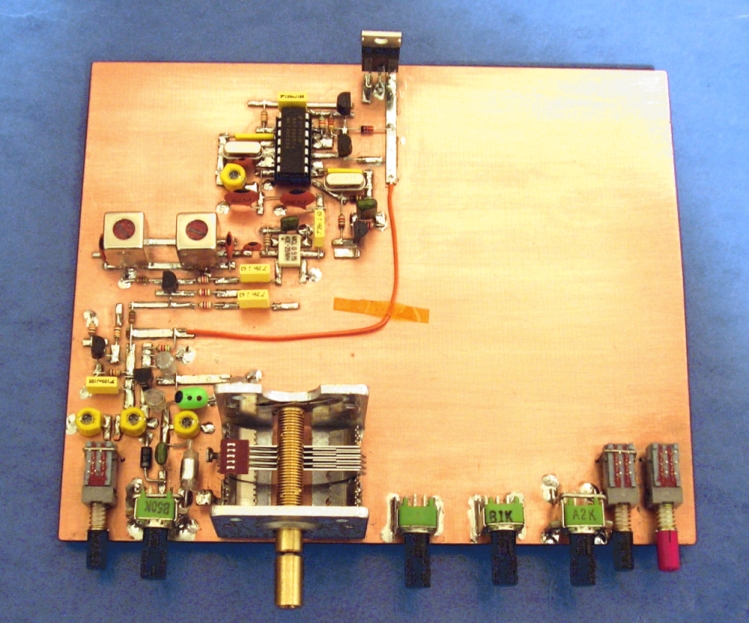
(2-06-2006) Manhattan pads made from .031" double sided copper clad.
 < >
< >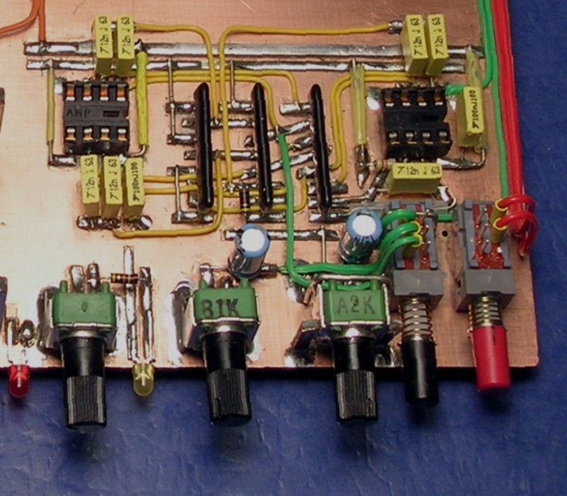
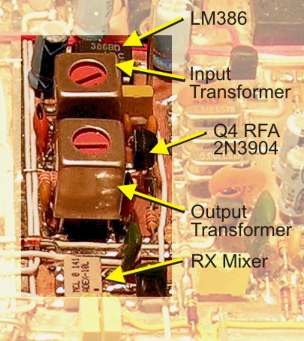
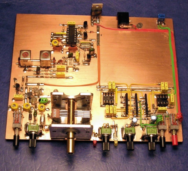
(2-08-2006) Audio filter section built using the SIP resistors.
Closer view. U2-U3 socketted for prototype testing.
So far, I've been able to maintain building it ± 1/8 inch of
Comment: Do not try this at home :-)
... it was quite tedious!
of the layout drawing.
However, it is very close to proposed PCB layout.
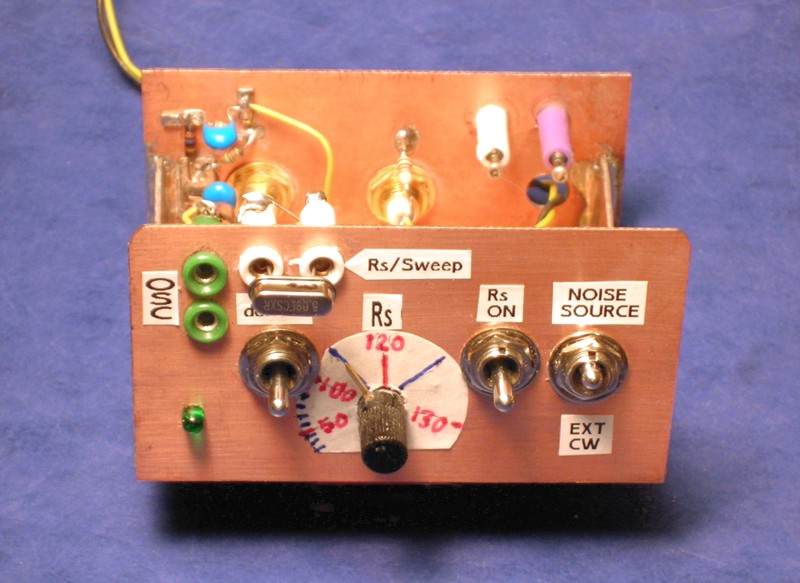
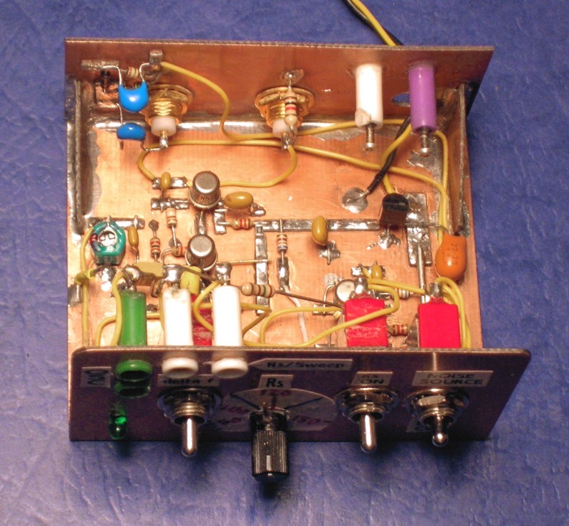
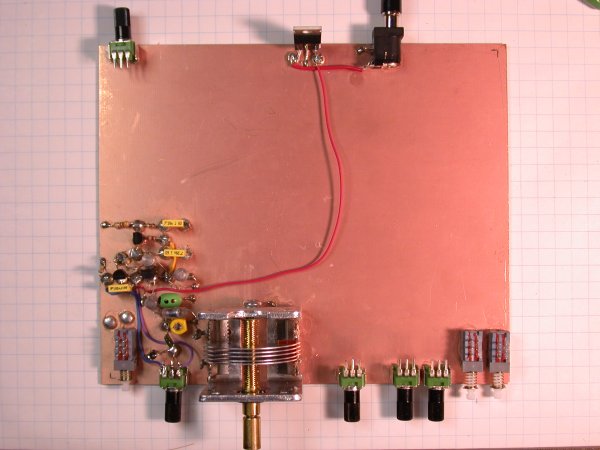
CRYSTAL
TEST SET
A couple of photos of the Crystal Test Set. I'll get my hand-drawn
schematic scanned in shortly. It consists of a colpitts oscillator
for testing the crystal frequency at no, and the desired load, for determining
crystal parameters. It also contains a noise source generator for
"sweeping" the crystal with a spectrum analyzer (or an external CW signal
generator) for determining the series resistance (Rs), CW and noise bandwidths,
insertion loss, etc.
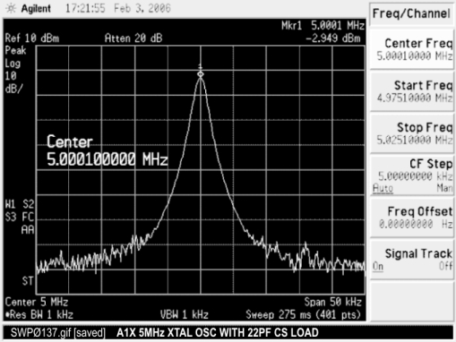
SPECTRUM ANALYZER DISPLAYS
of testing the HC-49US (low profile) 5MHz crystals with the crystal
test set
 <
>
<
>
The 5MHz crystal as an oscillator with 22pF load, yielding
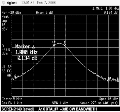
Sweeping the 5MHz crystal with CW, measuring
an oscillator frequency very close to the marked frequency.
the 3dB bandwidth at 1.0 KHz; RF IN=60dBm
 <
>
<
>
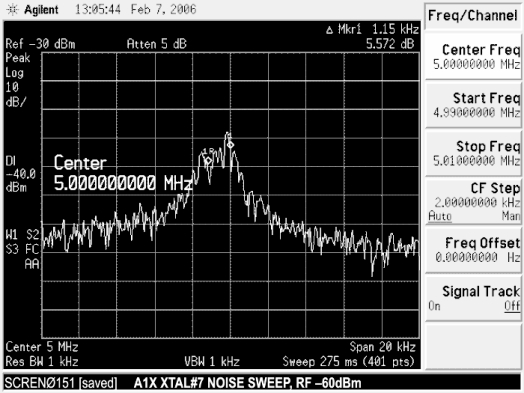
Sweeping the 5MHz crystal with NOISE. This is an instantaneous
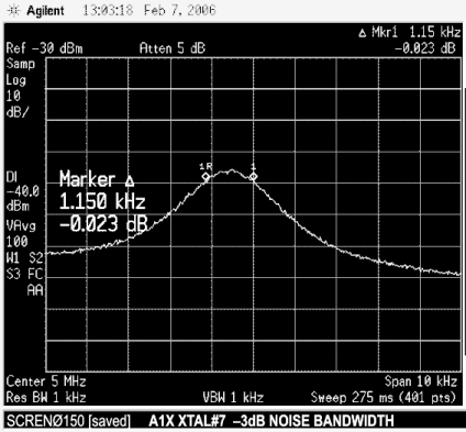
Sweeping the 5MHz crystal with NOISE, measuring
sweep, difficult to measure. Input noise power = 60dBm.
the 3dB bandwidth at 1.150 KHz, Input power=60dBm
Notice +20dB rise in noise floor from CW sweep. This is what
Noise integrated/averaged to make measurement.
the IF filter really sees in the real world.
AA0XX, CRAIG JOHNSON
PHOTOS
 <
>
<
>